● ISO 9001:2015 Certified · BIS Licensed (IS 1180) · Type Tested at CPRI & ERDA · Brand Heritage Since 1970
● ISO 9001:2015 Certified · BIS Licensed (IS 1180) · Type Tested at CPRI & ERDA · Brand Heritage Since 1970
Home / Manufacturing
A purpose-built transformer works at KIADB Bidadi, Bengaluru — with EOT cranes, LV/HV winding machines, vacuum drying and a full-fledged test field under one roof.
Factory Overview
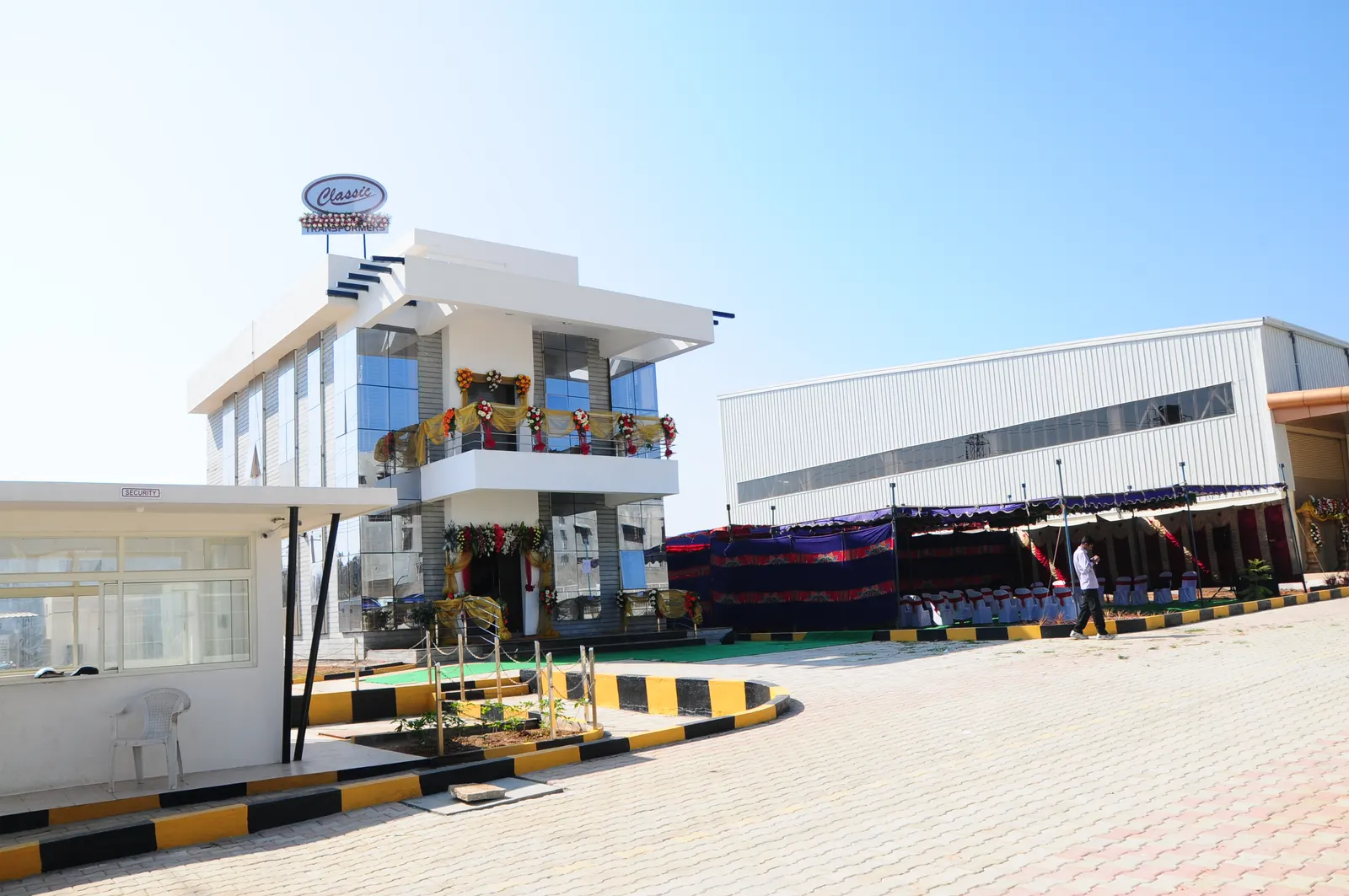
“Classic Technolines Pvt. Ltd.” is a small-scale industry spread over 1.25 acres with 20,000 sq ft of built-up area, which includes 12,000 sq ft of transformer manufacturing area. The balance area is covered by the office block, power house, D.G. house, transformer yard, paint shop, pressure testing shop, scrap yard and staff amenities.
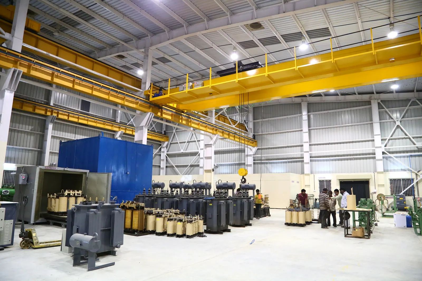
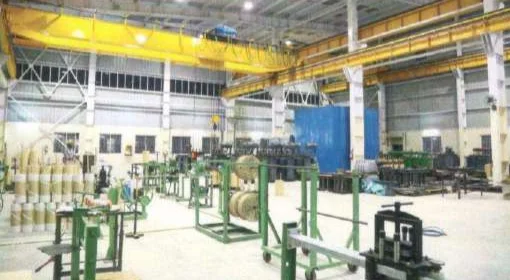
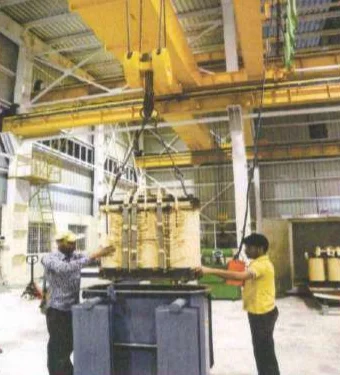
We have two 24-hour diesel generator back-ups — one for power transformers and the other for distribution transformers. The unit is equipped with 20-ton and 10-ton EOT cranes with 60 ft and 40 ft spans respectively, pneumatic tools on the production line that make work faster and more accurate, a full-fledged test field and the latest LV/HV winding machines suitable for distribution and power transformer manufacturing.

Manufacturing campus
Built-up area
Transformer manufacturing area
EOT cranes — 60 ft & 40 ft spans
Diesel generator back-ups
Latest winding machines
In-house test field
& pressure testing shop
Total Manufacturing Process Key Features
From CRGO core building to final dispatch, every Classic transformer follows a controlled, documented process in our own works.
Step 01
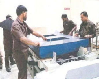
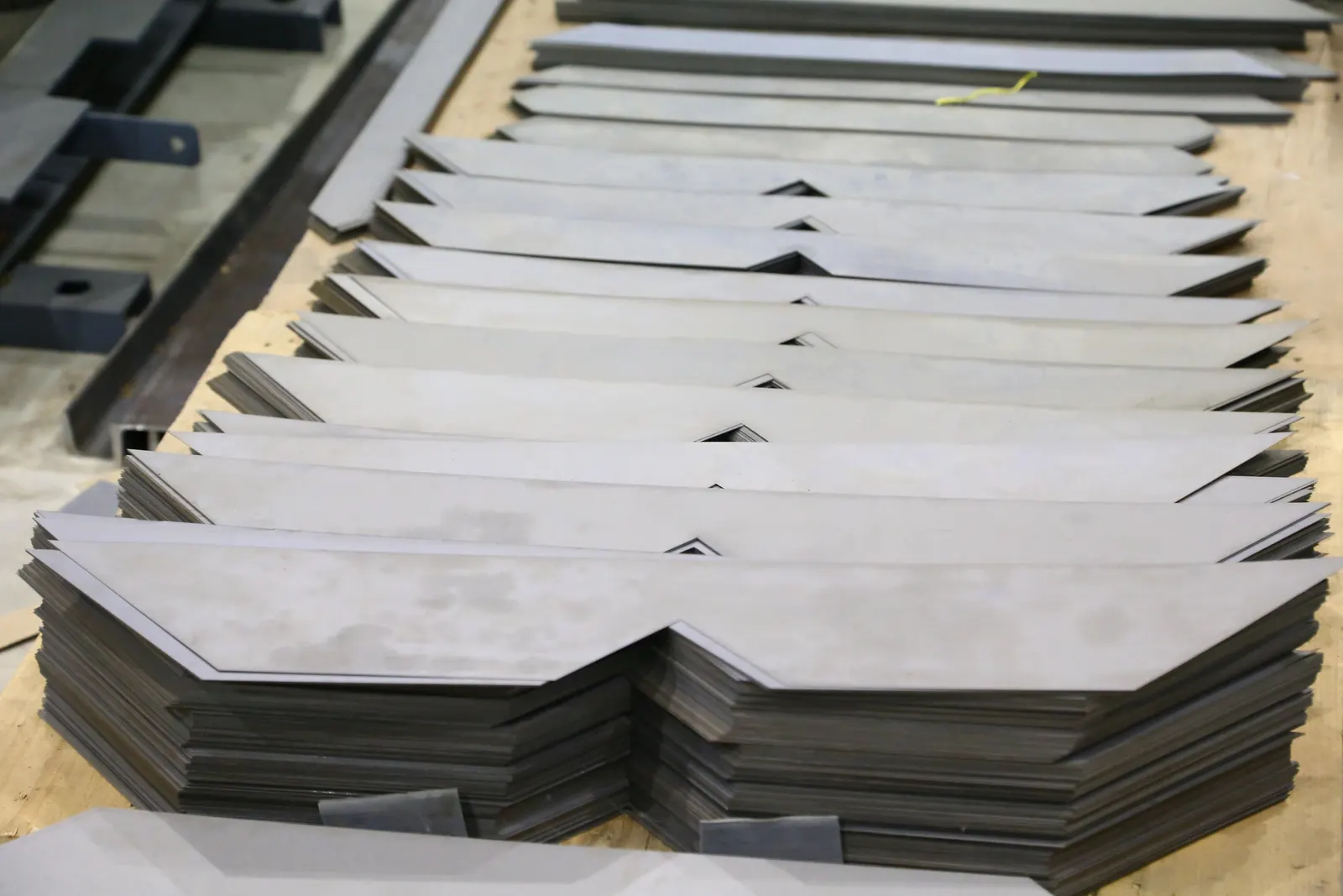
Transformer cores are built from CRGO low-loss silicon steel laminations. The use of Hi-B grade, laser-scribed laminations significantly reduces no-load losses, no-load current and noise levels. Laminations are assembled on a special core-forming fixture with step-lap or mitred joints at the corners for a streamlined flux path.
Core limbs held with resin-bonded glass bands — no limb bolts
Yokes clamped by solid mild-steel plates with yoke studs
High rigidity to withstand transport shocks and short circuits
Step 02
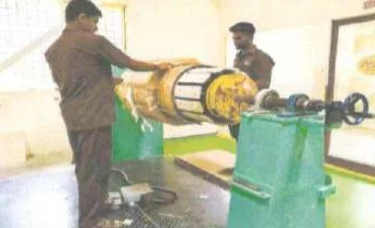
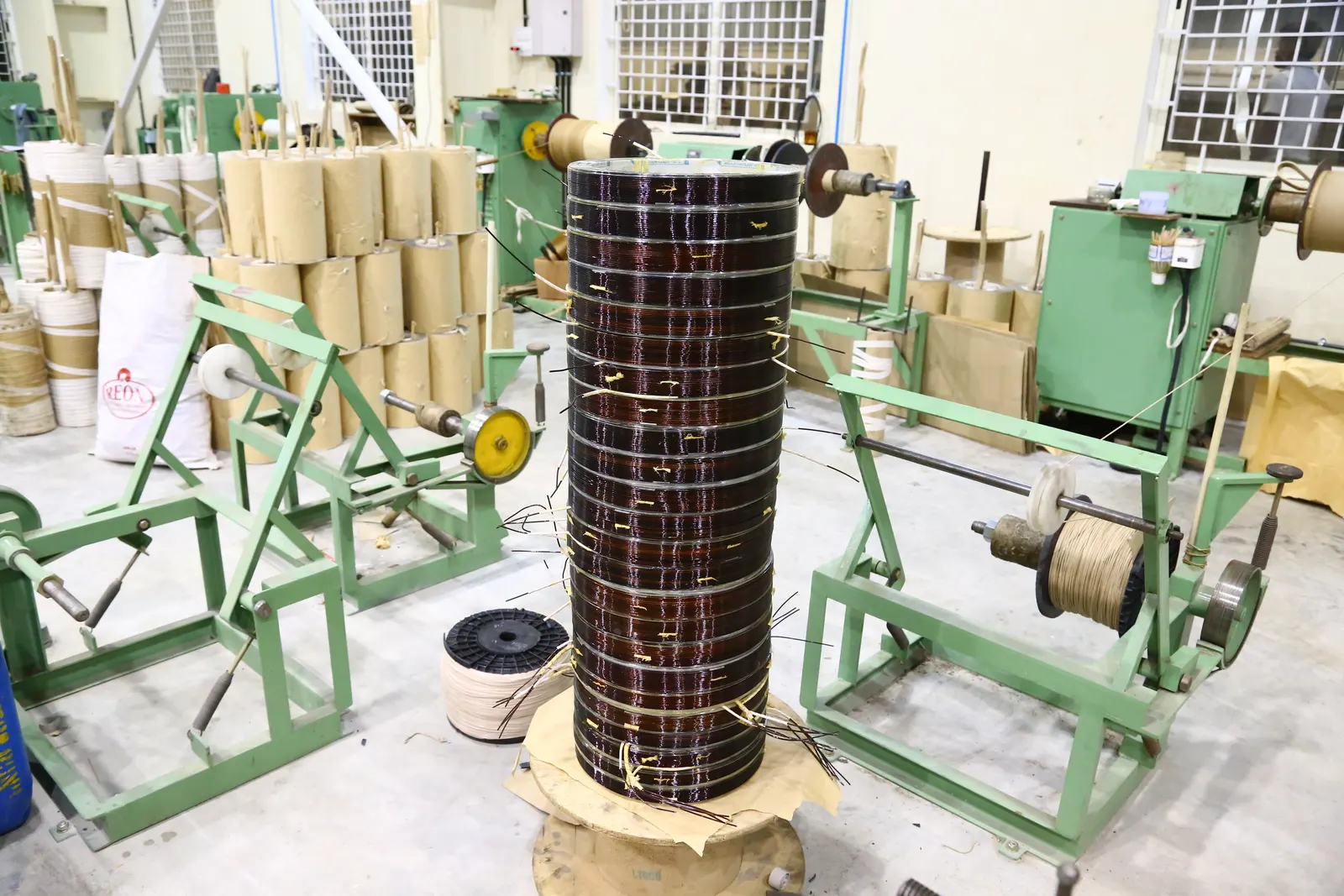
Electrolytic-grade copper or aluminium conductors (DPC / TPC / MPC) are wound on horizontal winding machines by experienced techno-craftsmen in a clean, positive-pressure environment. Pre-compressed radial cooling ducts ensure effective heat dissipation into the oil and eliminate hot spots.
Helical / disc coils for high-voltage windings
Interleaved or shielded construction for uniform voltage distribution
Finished coils compressed in 100-ton pressing jigs
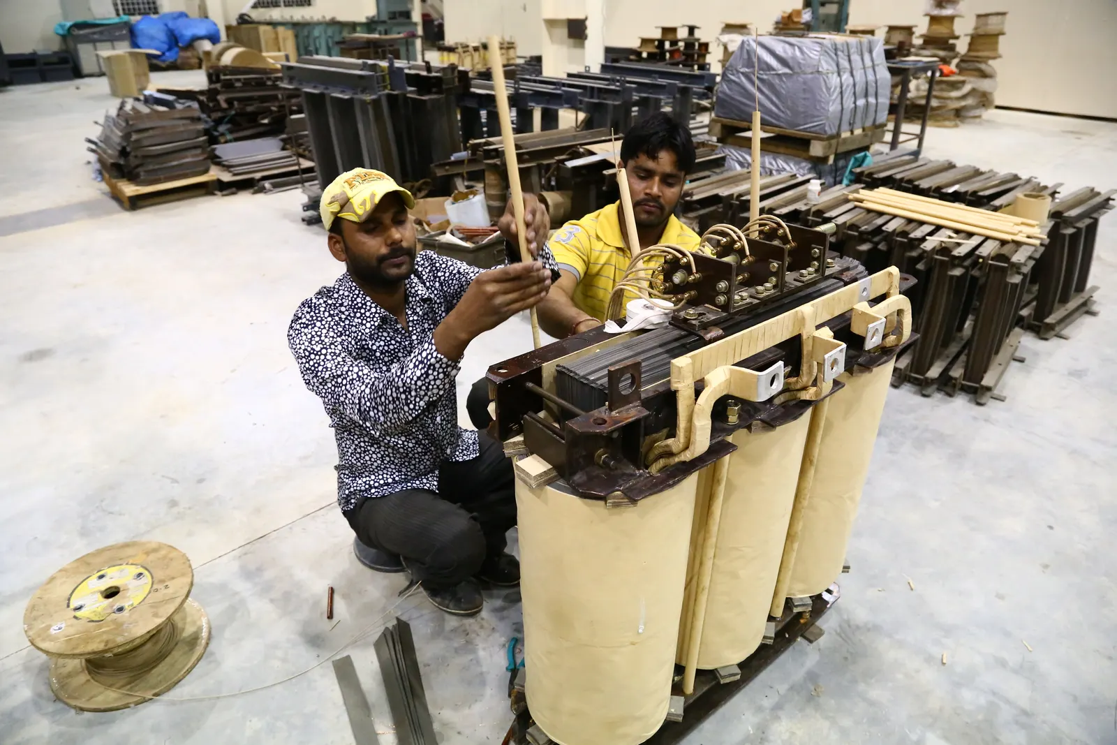
Step 03
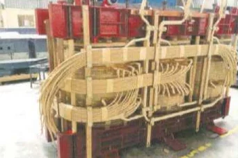
Windings are rigidly supported by a common pressure ring of densified wood at top and bottom for precise alignment. Profiled angle rings between HV and LV windings reduce voltage stress, and all winding ends and tapping leads are connected with extra-flexible insulated copper cables, rigidly braced in position.
Densified-wood pressure rings
Angle rings between HV and LV windings
In oil-forced units, oil circulated through insulated pipes

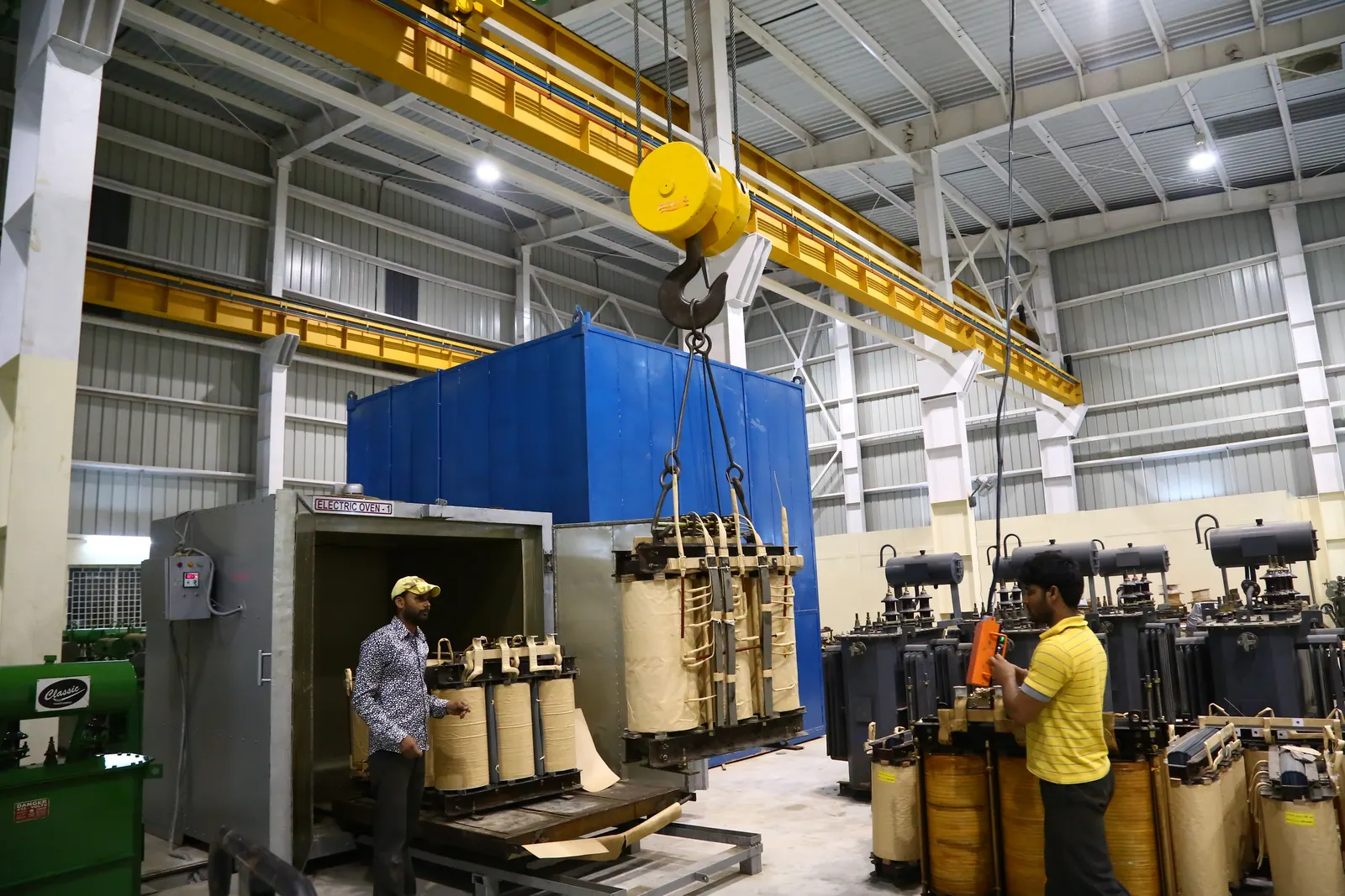
Step 04
The completed core-coil assembly is dried to less than 0.5% moisture content in an automated hot-air / vacuum drying chamber. The assembly is placed in a rigidly sealed chamber at a set temperature of 95 °C, and moisture evacuation continues until the required insulation resistance (IR) value is achieved.
Automated hot-air / vacuum chamber
Moisture below 0.5%
Process continued until target IR value is reached
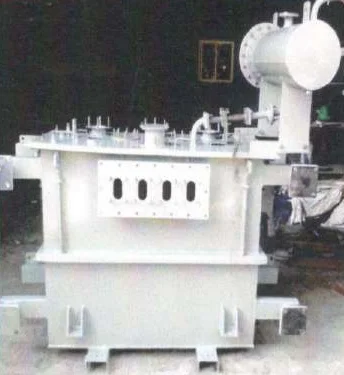
Step 05
Tanks are built from mild-steel plates to withstand full vacuum, with welders qualified to ASME Section IX. Tanks are designed to roll and skid in specified directions, and lugs for jacking, lifting and hauling are routinely dye-penetration tested. Surfaces are shot blasted to SA 2.5, coated with zinc-rich primer and finished in epoxy or polyurethane paint.
Welded or bolted top-cover designs
Spray galvanizing offered on request
Minimum-width jointless gaskets for leak-free sealing
Step 06
Rectangular or octagonal tanks with fin-type radiators are leak tested with an air pressure test before painting. The core-coil assembly is lowered into the tank and fastened, and the transformer is completed with bushings, OLTC, conservator, valves, cable boxes and radiators.
Air pressure leak test on every tank
High-quality cork-rubber cover gaskets
Uni- or bi-directional rollers as required
Step 07
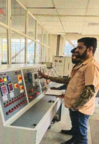
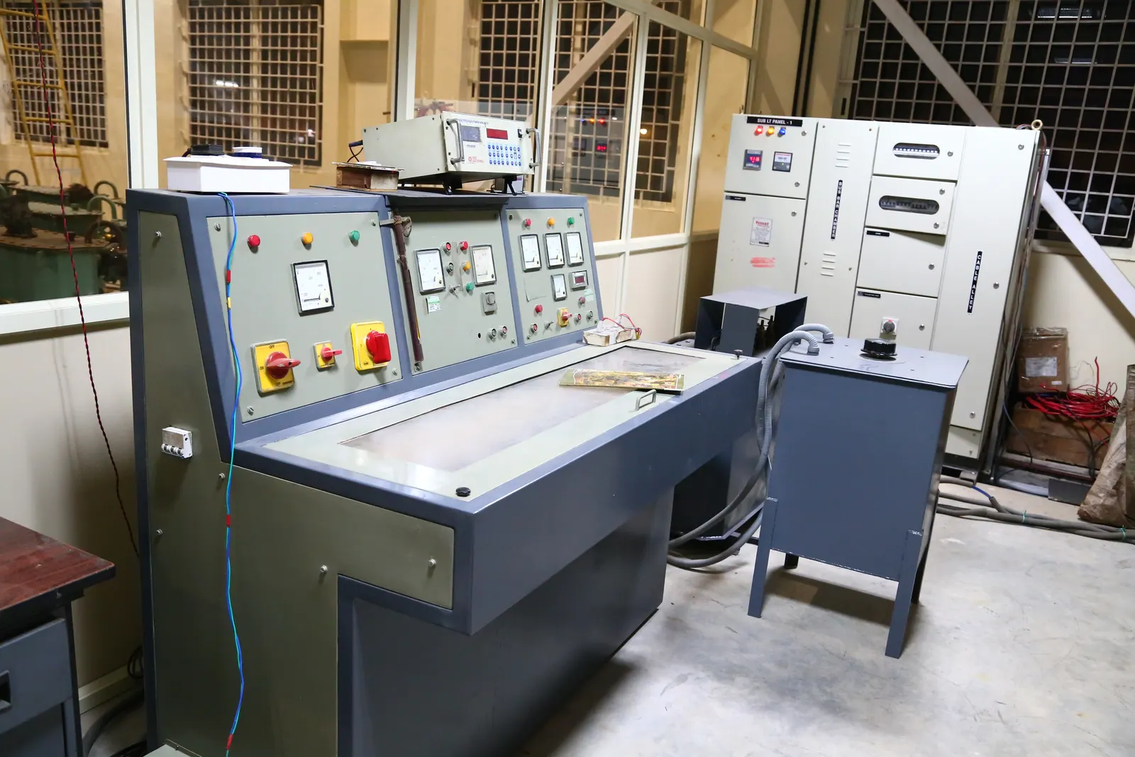
Routine, type and special tests are performed according to the latest IS, IEC and IEEE standards and customer requirements. Special tests such as short-circuit withstand and lightning impulse can also be performed at NABL-accredited laboratories such as CPRI and ERDA.
In-house test field for routine tests
Type tests at CPRI, ERDA and ERTO
Customer witness testing on request
Step 08
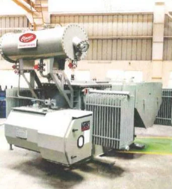
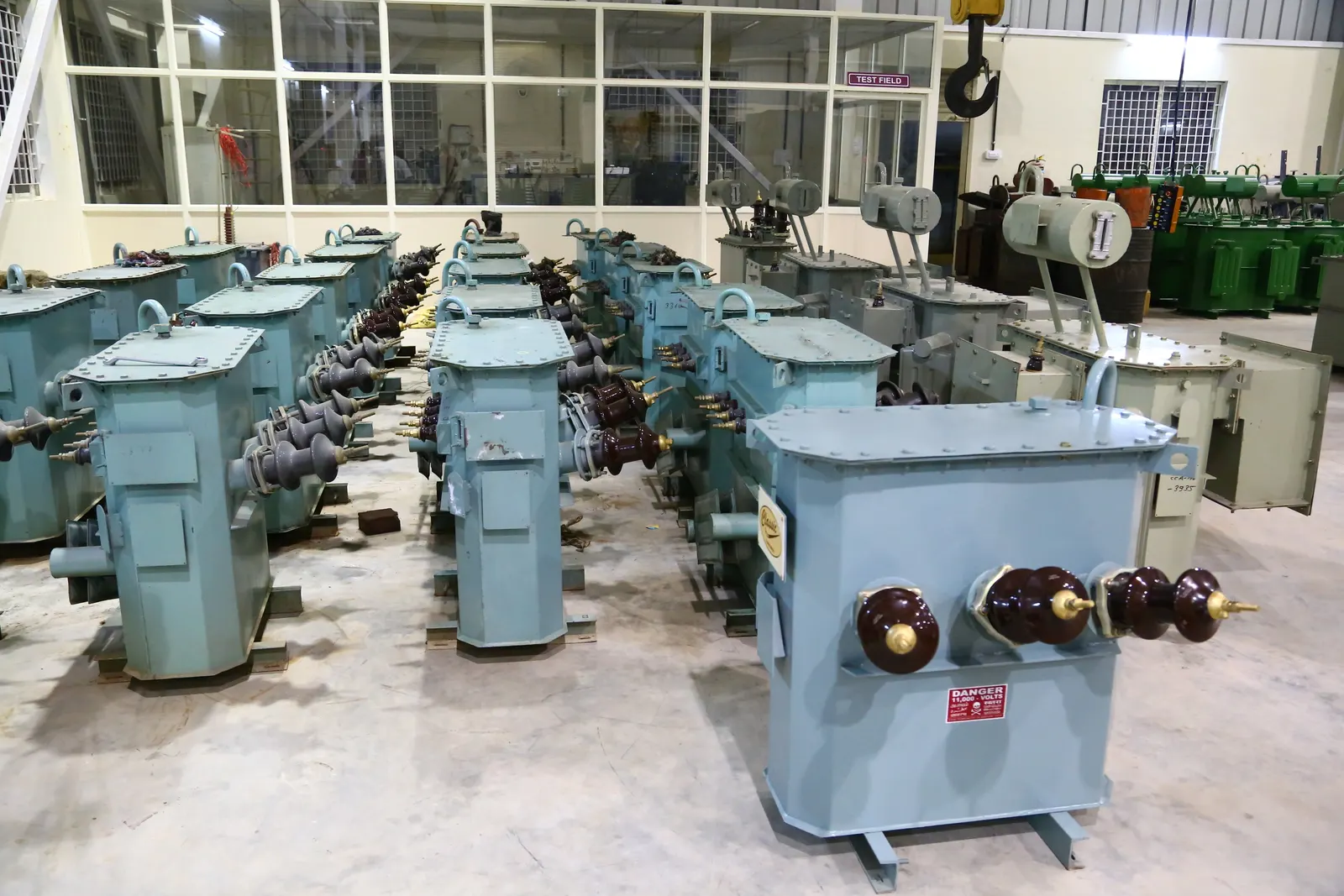
The main tank and accessories are transported as per the planned design and logistics. Accessories, oil barrels and tools are first packed in polyethylene and shipped in standard trucks with shipping marks and contents specified, for damage-free delivery.
Accessories packed in polyethylene
Clear shipping marks and contents lists
Planned logistics for damage-free shipment
Facilities
20-ton and 10-ton EOT cranes with 60 ft and 40 ft spans.
Latest LV/HV horizontal winding machines.
Full-fledged test field with dedicated control panels.

Finished transformers prepared in the transformer yard.
